# Causal Discovery: Latent Variables
```{r}
#| include: false
suppressPackageStartupMessages({
library(pcalg)
library(graph)
library(igraph)
library(ggplot2)
library(knitr)
})
# ─── igraph helpers ──────────────────────────────────────────────────────────
graphnel_to_ig <- function(g_nel) {
ig <- igraph::graph_from_graphnel(g_nel)
el <- igraph::as_edgelist(ig)
fwd <- paste(el[,1], el[,2]); rev_ <- paste(el[,2], el[,1])
is_undir <- fwd %in% rev_
seen <- character(0); keep <- logical(nrow(el))
for (k in seq_len(nrow(el))) {
if (!is_undir[k]) { keep[k] <- TRUE; next }
key <- paste(sort(c(el[k,1], el[k,2])), collapse="|")
if (key %in% seen) { keep[k] <- FALSE } else { seen <- c(seen, key); keep[k] <- TRUE }
}
ig2 <- igraph::delete_edges(ig, which(!keep))
igraph::E(ig2)$undirected <- is_undir[keep]
igraph::V(ig2)$label.color <- "black"
ig2
}
# Build an igraph from a pcalg PAG amat (0=none,1=circle,2=arrowhead,3=tail).
# Dashed edges = at least one circle endpoint; double arrows = both arrowheads.
pag_to_ig <- function(amat, labels = rownames(amat)) {
p <- nrow(amat)
frm <- integer(0); too <- integer(0); amode <- integer(0); lty <- integer(0)
for (i in seq_len(p-1)) for (j in seq.int(i+1, p)) {
if (amat[i,j]==0 && amat[j,i]==0) next
mi <- amat[i,j]; mj <- amat[j,i]
frm <- c(frm,i); too <- c(too,j)
am <- if (mi==2 && mj==2) 3L else if (mj==2) 1L else if (mi==2) 2L else 0L
amode <- c(amode, am)
lty <- c(lty, if (mi==1 || mj==1) 2L else 1L)
}
g <- igraph::make_empty_graph(n=p, directed=TRUE)
igraph::V(g)$name <- labels
igraph::V(g)$label.color <- "black"
if (length(frm)) {
g <- igraph::add_edges(g, c(rbind(frm, too)))
igraph::E(g)$amode <- amode; igraph::E(g)$lty <- lty
}
g
}
plot_ig <- function(g, main="", layout=NULL) {
if (is.null(layout)) {
dir_idx <- if (!is.null(igraph::E(g)$amode))
which(igraph::E(g)$amode %in% c(1L,2L))
else seq_len(igraph::ecount(g))
g_dir <- if (length(dir_idx)>0) igraph::subgraph_from_edges(g,dir_idx) else g
layout <- igraph::layout_with_sugiyama(g_dir)$layout
}
n_e <- igraph::ecount(g)
am <- if (!is.null(igraph::E(g)$amode)) igraph::E(g)$amode else
if (!is.null(igraph::E(g)$undirected)) ifelse(igraph::E(g)$undirected,0L,1L) else
rep(1L,n_e)
lt <- if (!is.null(igraph::E(g)$lty)) igraph::E(g)$lty else rep(1L,n_e)
plot(g, layout=layout, main=main,
vertex.size=26, vertex.color="white", vertex.frame.color="black",
vertex.label.cex=0.9, vertex.label.color="black", vertex.label.font=2,
edge.arrow.size=0.45, edge.arrow.mode=am, edge.color="black",
edge.lty=lt, edge.curved=0)
}
```
The previous chapter assumed all causally relevant variables were observed.
That is a strong assumption. In economics, ability, demand shocks, and peer
effects are often unobserved.
When latent confounders exist, PC and GES can give the wrong graph. Here I
use `pcalg` algorithms designed for latent variables.
### Why PC fails with latent variables
Suppose the true graph is $X \leftarrow U \rightarrow Y$ where $U$ is unobserved. In the observed data, $X$ and $Y$ are marginally correlated (through $U$) and no observed conditioning set separates them. PC will incorrectly draw an edge $X - Y$ and may orient it as $X \to Y$ or $X \leftarrow Y$, neither of which exists in the truth.
With even one hidden common cause, the conditional independences among
observed variables may not correspond to any DAG on the observed variables
alone. We need a MAG/PAG representation.
## Maximal Ancestral Graphs and PAGs
With latent variables, the appropriate representation is a **Maximal Ancestral Graph (MAG)**. Over a set of *observed* variables $\mathbf{O}$, a MAG encodes:
- $X \to Y$: $X$ is an ancestor of $Y$ in the full DAG
- $X \leftrightarrow Y$: $X$ and $Y$ have a common hidden ancestor (hidden confounder)
- No edge: $X \perp\!\!\!\perp Y \mid Z$ for some $Z \subseteq \mathbf{O} \setminus \{X, Y\}$
The MAG over observed variables summarizes the causal and confounding
relationships visible in the observed data without naming the latent
variables.
Just as DAGs have Markov equivalence classes represented by CPDAGs, MAGs have equivalence classes represented by **Partial Ancestral Graphs (PAGs)**. In a PAG, the mark $\circ$ on an edge endpoint means "could be arrowhead or tail in some member of the equivalence class."
| PAG mark | Meaning | Economic interpretation |
|---|---|---|
| $X \to Y$ | $X$ causes $Y$ in every equivalent MAG | Robust causal direction |
| $X \circ\!\!\to Y$ | Some MAGs have $X \to Y$, others $X \leftrightarrow Y$ | Direction uncertain |
| $X \leftrightarrow Y$ | Hidden common cause in every equivalent MAG | Definite unmeasured confounder |
| $X \;\circ\!\!-\!\!\circ\; Y$ | Could be $\to$, $\leftarrow$, or $\leftrightarrow$ | Maximally uncertain |
**Reading a PAG for policy purposes:**
- A definite $X \to Y$ edge is the most useful finding: any intervention on $X$ propagates to $Y$ regardless of which specific MAG the data came from.
- A definite $X \leftrightarrow Y$ edge is a warning: before using regression of $Y$ on $X$ to estimate a causal effect, you must address the hidden confounder — through an instrument, a proxy, or a natural experiment.
- $\circ$ marks indicate what you *don't* know. Additional data, temporal ordering, or experimental variation can resolve them.
## FCI and RFCI: The R Toolkit
R's `pcalg` package provides two algorithms for the latent-variable case:
| Algorithm | Output | Cost |
|---|---|---|
| **FCI** (Spirtes, Meek & Richardson, 1995) | Full PAG (skeleton + all orientation marks) | Expensive: the Possible-D-SEP stage performs many additional CI tests |
| **RFCI** (Colombo, Maathuis, Kalisch & Richardson, 2012) | PAG with possibly fewer/weaker orientations | Cheaper: skips the Possible-D-SEP tests |
RFCI can give fewer orientations than FCI, and its skeleton converges to a
(uniquely defined) *supergraph* of the true PAG skeleton — in special
configurations it retains an edge FCI would remove, though on many graphs the
two coincide. It is a faster screening tool.
## Simulation with Hidden Variables
We reuse the same 8-node Gaussian linear DAG from the previous chapter --- same
seed, same `randomDAG` call with edge probability 0.35 and coefficients drawn
from $[0.25, 1]$, same $n = 2000$ draws with standard normal errors --- and then
hide two of the nodes, $X_3$ and $X_6$, treating them as unobserved
confounders. The algorithms below see a $2000 \times 6$ matrix; the full
8-column matrix is kept only to construct the truth.
The aim is to see what latent confounding costs. The previous chapter's PC
reached a skeleton F1 of 0.952 with all eight variables observed. Nothing about
the DGP changes here except which columns we are allowed to look at.
```{r}
set.seed(2025)

n_vars     <- 8
n_samples  <- 2000
edge_prob  <- 0.35
latent_idx <- c(3, 6)
obs_idx    <- setdiff(1:n_vars, latent_idx)
all_labels <- paste0("X", 1:n_vars)
obs_labels <- all_labels[obs_idx]

true_dag   <- randomDAG(n_vars, prob = edge_prob, lB = 0.25, uB = 1)
nodes(true_dag) <- all_labels
data_full  <- rmvDAG(n_samples, true_dag, errDist = "normal")
colnames(data_full) <- all_labels
data_obs   <- data_full[, obs_idx]
n_obs      <- length(obs_idx)

sprintf("Total variables: %d   Hidden: %s   Observed: %d",
        n_vars, paste(all_labels[latent_idx], collapse = ", "), n_obs)
```
### True structure over observed variables
Two observed variables are adjacent in the MAG iff no subset of the *observed* variables d-separates them in the full DAG. We compute this with `pcalg::dsep`.
```{r}
all_subsets <- function(xs) {
  out <- list(character(0))
  for (k in seq_along(xs)) out <- c(out, combn(xs, k, simplify = FALSE))
  out
}

# Ancestors of a node in a graphNEL DAG (excluding the node itself).
ancestors_of <- function(dag, target) {
  ie <- inEdges(dag)
  visited <- character(0)
  queue   <- target
  while (length(queue)) {
    cur <- queue[1]; queue <- queue[-1]
    if (cur %in% visited) next
    visited <- c(visited, cur)
    queue   <- c(queue, ie[[cur]])
  }
  setdiff(visited, target)
}

# Simplified "true MAG" over observed nodes as a pcalg-encoded PAG amat:
# directed edges where one observed node is an ancestor of the other in the
# full DAG, bidirected edges where neither is an ancestor of the other.
#
# NOTE: this is a SIMPLIFIED oracle for the skeleton/F1 comparison below,
# not a full authoritative MAG. A true MAG projection can carry more
# subtle endpoint marks when directed and confounding paths coexist
# (e.g. an edge that is both a causal ancestor and confounded). Use this
# as an observed-variable adjacency oracle, not as a definitive
# MAG/PAG endpoint ground truth.
true_mag_amat <- function(dag, observed_names) {
  p <- length(observed_names)
  amat <- matrix(0L, p, p, dimnames = list(observed_names, observed_names))
  for (i in seq_len(p - 1)) for (j in seq.int(i + 1, p)) {
    u <- observed_names[i]; v <- observed_names[j]
    others <- setdiff(observed_names, c(u, v))
    sep <- any(vapply(all_subsets(others),
                      function(S) dsep(u, v, S, dag),
                      logical(1)))
    if (sep) next
    anc_u <- ancestors_of(dag, u)
    anc_v <- ancestors_of(dag, v)
    # pcalg amat.pag convention: amat[i, j] is the mark AT j
    # (u -> v means arrowhead (2) at v, tail (3) at u)
    if      (u %in% anc_v) { amat[i, j] <- 2L; amat[j, i] <- 3L }   # u -> v
    else if (v %in% anc_u) { amat[i, j] <- 3L; amat[j, i] <- 2L }   # v -> u
    else                   { amat[i, j] <- 2L; amat[j, i] <- 2L }   # u <-> v
  }
  amat
}

# Skeleton version (1 wherever an edge exists, ignoring direction) — used in
# the Monte Carlo F1 comparison below.
true_mag_skel <- function(dag, observed_names) {
  a <- true_mag_amat(dag, observed_names)
  (a != 0L) * 1L
}

amat_true_pag  <- true_mag_amat(true_dag, obs_labels)
amat_true_mag  <- (amat_true_pag != 0L) * 1L  # skeleton for F1 comparisons

# igraph representations used for plotting
ig_true_full <- graphnel_to_ig(true_dag)   # full 8-node DAG
ig_true_pag  <- pag_to_ig(amat_true_pag, obs_labels)   # true MAG over obs nodes

# Shared layout: compute from full DAG, subset coords for observed-node plots
full_layout  <- igraph::layout_with_sugiyama(ig_true_full)$layout
obs_layout   <- full_layout[obs_idx, ]     # positions of the observed nodes
rownames(obs_layout) <- obs_labels

sprintf("True MAG skeleton edges (over %d observed nodes): %d",
        n_obs, sum(amat_true_mag) / 2)
```
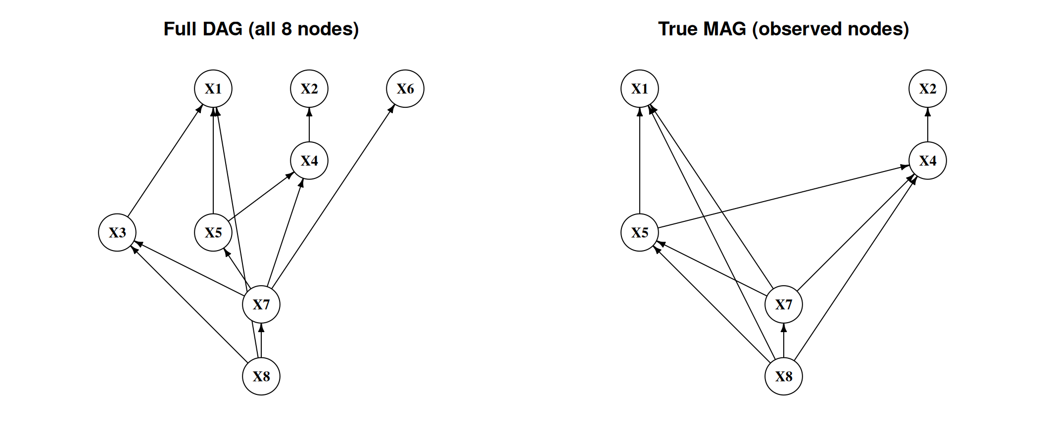
This is the first thing to notice, before any algorithm runs. The full DAG has
11 edges among 8 nodes. The true MAG over the 6 observed nodes has 10 edges
among 15 possible pairs, a density of two thirds. Hiding two variables did not
simplify the problem; it made the graph much denser, because every pair of
observed nodes sharing a hidden parent acquires an edge that was not there
before. That densification is the cost of latent confounding, and it is why the
F1 scores below sit well under the 0.952 that PC managed with everything
observed.
```{r}
#| label: fig-latent-dag
#| fig-cap: "Full DAG (all 8 nodes) and the true MAG skeleton over observed variables. The MAG skeleton includes both direct paths and paths through hidden nodes."
#| fig-width: 11
#| fig-height: 4.5
op <- par(mfrow = c(1, 2), mar = c(1, 1, 3, 1))
plot_ig(ig_true_full, layout = full_layout, main = "Full DAG (all 8 nodes)")
plot_ig(ig_true_pag,  layout = obs_layout,  main = "True MAG (observed nodes)")
par(op)
```
## FCI Algorithm
FCI is the extension of PC for latent variables. It starts from a complete
graph, removes edges with CI tests, and then uses orientation rules that can
produce bidirected edges for hidden common causes.
**How FCI extends PC:**
1. **Phase 1 (skeleton):** Same as PC — remove edges via CI tests with growing conditioning sets.
2. **Phase 2 (initial orientation):** Mark all edge endpoints as $\circ$ (uncertain); orient unshielded colliders as in PC.
3. **Phase 3 (Possible-D-SEP pruning):** For each remaining edge $X - Y$, compute the **Possible-D-SEP** sets and run *additional* CI tests conditioning on their subsets, removing further edges. With latent variables, two non-adjacent nodes need not be separable by a subset of their neighbors — this stage is what makes FCI's skeleton differ from PC's, and it is the expensive part (the number of subsets can grow exponentially). Colliders are then re-oriented on the pruned skeleton.
4. **Phase 4 (rule propagation):** Apply the 10 orientation rules of @zhang-2008-orientation-rules (as implemented in `pcalg`) that propagate known marks without creating contradictions, including rules that can produce definite $\to$ and $\leftrightarrow$ edges. These rules perform no CI tests and are computationally cheap.
The extra marks let FCI say what is known and what remains uncertain, but the
output is harder to read than a DAG.
```{r}
make_counted_ci <- function(suff_stat) {
  count <- 0L
  ci <- function(x, y, S, suffStat) {
    count <<- count + 1L
    gaussCItest(x, y, S, suffStat)
  }
  list(ci = ci, count = function() count)
}

sig_level <- 0.01
suff_obs  <- list(C = cor(data_obs), n = n_samples)

ci_fci   <- make_counted_ci(suff_obs)
fci_fit  <- fci(suff_obs, ci_fci$ci, labels = obs_labels,
                alpha = sig_level, verbose = FALSE)
ci_tests_fci <- ci_fci$count()
```
```{r}
# pcalg PAG amat encoding: 0 = no edge, 1 = circle, 2 = arrowhead, 3 = tail.
# An edge between i and j is described by amat[i,j] (the mark AT j)
# and amat[j,i] (the mark AT i).
pag_skeleton_amat <- function(amat) {
  out <- (amat != 0 | t(amat) != 0) * 1L
  diag(out) <- 0L
  out
}

f1_skel <- function(amat_true, amat_est) {
  diag(amat_true) <- diag(amat_est) <- 0
  tp <- sum(amat_true & amat_est) / 2
  fp <- sum(!amat_true & amat_est) / 2
  fn <- sum(amat_true & !amat_est) / 2
  if (tp == 0) 0 else 2 * tp / (2 * tp + fp + fn)
}

skel_fci  <- pag_skeleton_amat(fci_fit@amat)
f1_fci_v  <- f1_skel(amat_true_mag, skel_fci)
ig_fci    <- pag_to_ig(fci_fit@amat, obs_labels)
sprintf("FCI:    skeleton F1 = %.3f   CI tests = %d", f1_fci_v, ci_tests_fci)
```
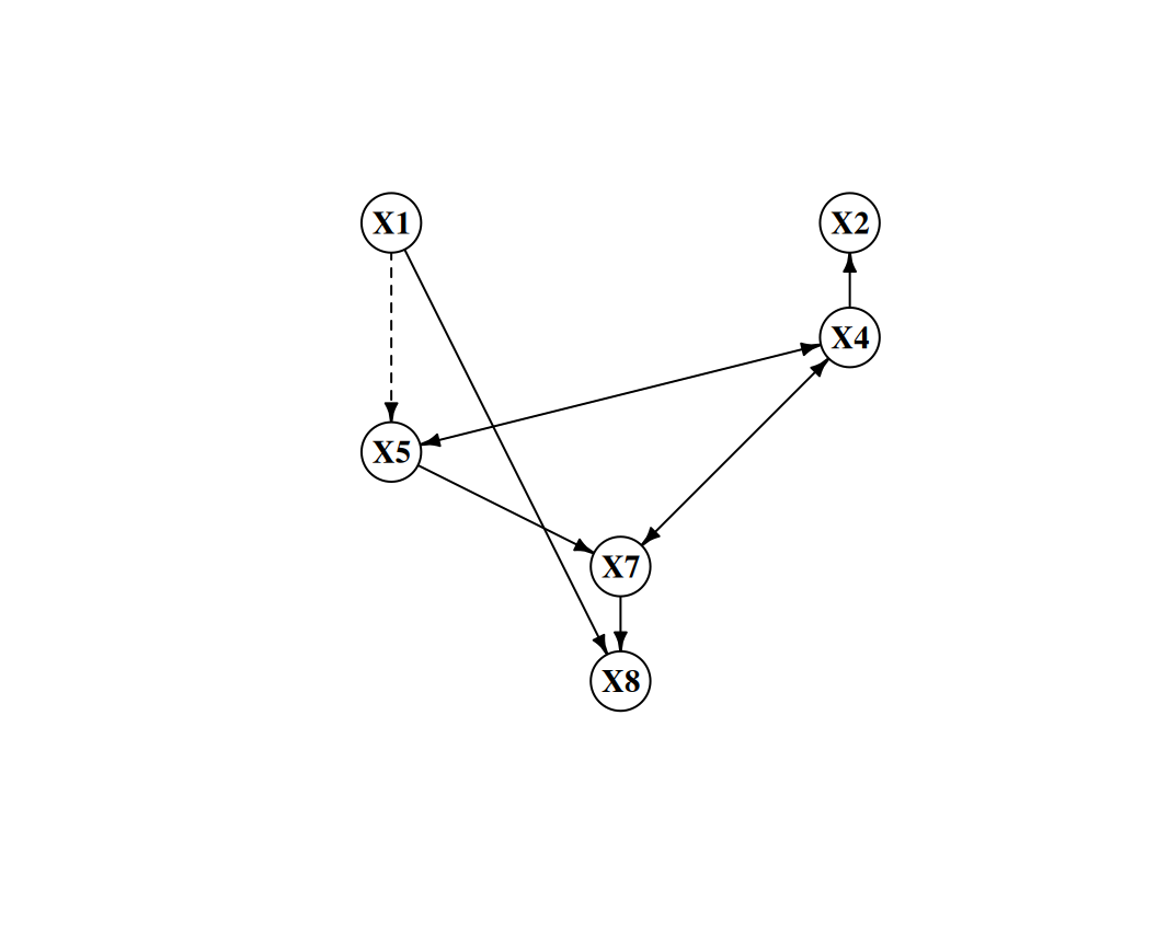
FCI recovers the skeleton with an F1 of 0.824, using 165 CI tests. That is a
long way below PC's 0.952 on the same underlying DAG with nothing hidden, and
the dense MAG is why: with two thirds of all pairs adjacent, there are few
conditional independences left to find, and each missed edge costs more.
```{r}
#| label: fig-fci-pag
#| fig-cap: "PAG estimated by FCI. Dashed edges indicate endpoints with circle (○) marks — orientations the algorithm could not determine. Solid double-headed arrows (↔) flag definite hidden common causes."
#| fig-width: 5.5
#| fig-height: 4.5
plot_ig(ig_fci, layout = obs_layout)
```
**Reading the PAG plot**
In `pcalg`'s plot output:
- A **plain arrow** $X \to Y$ is a definite cause *under the maintained discovery model* — causal Markov, faithfulness, acyclicity, a correct conditional-independence test, and no selection bias. Given those, $X$ is an ancestor of $Y$ in every equivalent MAG. It need not be a *direct* effect: the path may run through latent mediators (the DAG $X \to L \to Y$ with $L$ hidden yields the MAG $X \to Y$).
- A **double-headed arrow** $X \leftrightarrow Y$ is a definite hidden common cause.
- A **circle endpoint** is the $\circ$ mark — uncertain at that endpoint.
In practice for economic research: focus first on $\leftrightarrow$ edges — these flag definite confounding and tell you where IV or proxy strategies are needed. Then examine $\to$ edges — these are causal claims that survive across all statistically equivalent structures.
**When FCI gives wrong answers:** FCI assumes the CI tests are perfectly accurate (no finite-sample error). In practice, with small $n$ or many variables, some false CI decisions propagate through the 10 orientation rules. The skeleton quality (F1) is generally more reliable than the orientation quality.
## RFCI Algorithm
**RFCI** (Really Fast Causal Inference; Colombo et al., 2012) skips FCI's expensive **Possible-D-SEP pruning stage** entirely — the stage responsible for most of FCI's CI tests. To stay sound without it, RFCI adds a few extra CI tests of its own inside the collider and discriminating-path checks; the orientation-rule propagation is kept.
**Key differences from FCI:**
1. **Skeleton phase:** the PC-style skeleton search is the same, but RFCI does **not** run the Possible-D-SEP removals — this is where the savings come from, and why its skeleton can retain extra edges (it converges to a supergraph of the PAG skeleton).
2. **Collider check:** before orienting an unshielded triple as a collider, RFCI runs *additional* CI tests to verify the orientation — a modest extra cost that restores soundness without the Possible-D-SEP stage.
3. **Orientation output:** RFCI produces a *partial* PAG. Some edges that FCI orients are left as $\circ\!-\!\circ$ in RFCI; conversely, every mark RFCI does output is asymptotically correct under the same conditions.
In practice, the skeleton is often the main output: it tells us which pairs
need substantive attention. Full PAG orientations are useful, but they are
harder to defend.
```{r}
ci_rfci    <- make_counted_ci(suff_obs)
rfci_fit   <- rfci(suff_obs, ci_rfci$ci, labels = obs_labels,
                   alpha = sig_level, verbose = FALSE)
ci_tests_rfci <- ci_rfci$count()

skel_rfci  <- pag_skeleton_amat(rfci_fit@amat)
f1_rfci_v  <- f1_skel(amat_true_mag, skel_rfci)
ig_rfci    <- pag_to_ig(rfci_fit@amat, obs_labels)
sprintf("RFCI:   skeleton F1 = %.3f   CI tests = %d", f1_rfci_v, ci_tests_rfci)
```
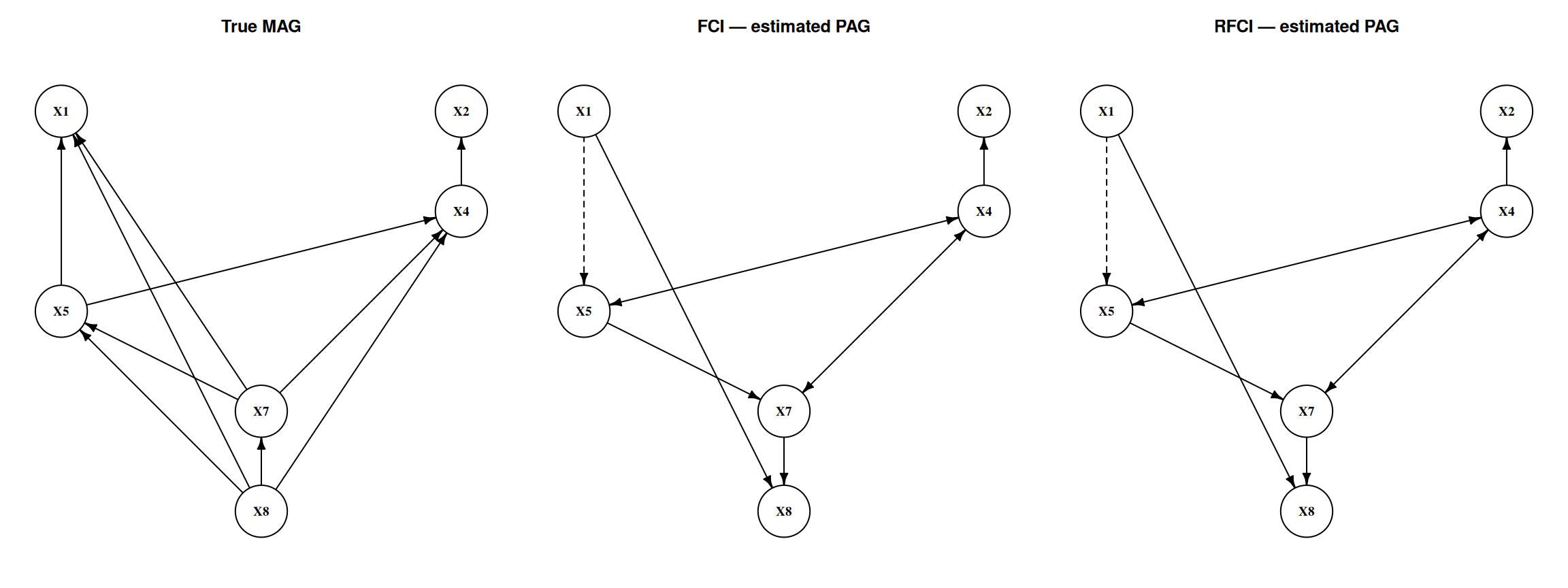
RFCI reaches the same skeleton F1 of 0.824 using 138 CI tests instead of 165, a
saving of 16%. On this dataset the Possible-D-SEP stage bought FCI nothing:
it ran 27 extra tests and removed no edge that mattered for the skeleton score.
**FCI vs. RFCI output: same plot type, fewer marks**
Both `fci()` and `rfci()` return `fciAlgo` objects and plot with the same `plot()` method. The visual difference is that RFCI's PAG typically has **more circle marks** — it has been more conservative about orientation. Edges that *do* receive an arrowhead or tail mark in RFCI are reliable.
If you only need the skeleton (the most common use case in large-$p$ screening problems), RFCI is the right default. If you need orientations to plan an IV strategy, run FCI on top.
## Comparison
```{r}
#| label: tbl-latent-comparison
#| tbl-cap: "Algorithm comparison on the latent-variable scenario (2 hidden nodes, n = 2000)"
kable(data.frame(
  Algorithm   = c("FCI", "RFCI"),
  Output      = c("Full PAG", "Skeleton + partial PAG"),
  Skeleton_F1 = round(c(f1_fci_v, f1_rfci_v), 3),
  CI_Tests    = c(ci_tests_fci, ci_tests_rfci)
), row.names = FALSE)
```
The two algorithms tie on skeleton recovery and RFCI is cheaper. One dataset is
not enough to conclude that, which is what the Monte Carlo below is for.
```{r}
#| label: fig-latent-skeletons
#| fig-cap: "True MAG vs. PAGs recovered by FCI and RFCI. Directed arrows are definite cause-to-effect; bidirected (↔) edges flag hidden common causes; circle (○) marks indicate orientations the algorithm could not resolve. RFCI typically leaves more circles than FCI because its orientation phase is deliberately more conservative."
#| fig-width: 12
#| fig-height: 4.5
op <- par(mfrow = c(1, 3), mar = c(1, 1, 3, 1))
plot_ig(ig_true_pag, layout = obs_layout, main = "True MAG")
plot_ig(ig_fci,      layout = obs_layout, main = "FCI — estimated PAG")
plot_ig(ig_rfci,     layout = obs_layout, main = "RFCI — estimated PAG")
par(op)
```
## Monte Carlo Evaluation
We repeat the whole exercise 100 times, drawing a fresh random DAG each time
and choosing a fresh pair of nodes to hide, so the results do not depend on one
graph or one unlucky choice of which variables are unobserved.
```{r}
#| cache: true
#| warning: false
#| message: false
evaluate_latent <- function(seed, n_vars = 8, n_samples = 2000,
                            edge_prob = 0.35, n_latent = 2, sig = 0.01) {
  set.seed(seed)
  labs <- paste0("X", 1:n_vars)
  dag  <- randomDAG(n_vars, prob = edge_prob, lB = 0.25, uB = 1)
  nodes(dag) <- labs
  d    <- rmvDAG(n_samples, dag, errDist = "normal")
  colnames(d) <- labs

  lat  <- sort(sample.int(n_vars, n_latent))
  obs  <- setdiff(seq_len(n_vars), lat)
  obs_labs <- labs[obs]
  d_obs <- d[, obs]
  ss    <- list(C = cor(d_obs), n = n_samples)

  true_skel <- true_mag_skel(dag, obs_labs)

  ci_f <- make_counted_ci(ss)
  fci_r <- fci(ss, ci_f$ci, labels = obs_labs, alpha = sig, verbose = FALSE)

  ci_r <- make_counted_ci(ss)
  rfci_r <- rfci(ss, ci_r$ci, labels = obs_labs, alpha = sig, verbose = FALSE)

  c(f1_fci  = f1_skel(true_skel, pag_skeleton_amat(fci_r@amat)),
    f1_rfci = f1_skel(true_skel, pag_skeleton_amat(rfci_r@amat)),
    ci_fci  = ci_f$count(),
    ci_rfci = ci_r$count())
}

mc <- as.data.frame(t(sapply(1:100, evaluate_latent)))

mc_summary <- data.frame(
  Method      = c("FCI", "RFCI"),
  Skeleton_F1 = round(c(mean(mc$f1_fci),  mean(mc$f1_rfci)),  3),
  CI_Tests    = round(c(mean(mc$ci_fci),  mean(mc$ci_rfci)),  1)
)
kable(mc_summary,
      caption = "Monte Carlo averages (100 replications, n = 2000, p = 8, 2 latent)",
      row.names = FALSE)
```
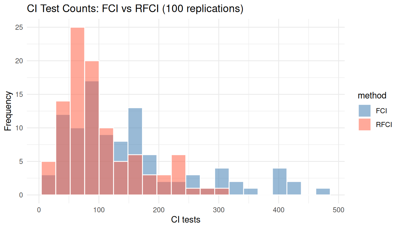
Averaged over 100 replications, FCI gets a skeleton F1 of 0.938 and RFCI 0.943,
while FCI uses 150.5 CI tests and RFCI 102.7. RFCI is 32% cheaper and loses
nothing on the skeleton.
Two cautions on reading that. The 0.005 F1 difference is not evidence that RFCI
recovers skeletons better; RFCI converges to a *supergraph* of the PAG
skeleton, so if anything theory points the other way, and a gap this small on
100 replications is noise. And the single dataset above scored 0.824 for both,
well below these averages --- that draw was one of the harder ones, as its
denser-than-average MAG would suggest.
What does survive is the cost result. Skipping the Possible-D-SEP stage is
where RFCI's savings come from, and on these graphs that stage is roughly a
third of FCI's work while contributing nothing measurable to skeleton accuracy.
```{r}
#| label: fig-latent-mc
#| fig-cap: "CI-test count distributions across 100 replications. By skipping the Possible-D-SEP tests, RFCI typically — though not always — runs fewer tests than FCI."
#| fig-width: 7
#| fig-height: 4
#| warning: false
#| message: false
mc_long <- data.frame(
  method = rep(c("FCI", "RFCI"), each = nrow(mc)),
  ci     = c(mc$ci_fci, mc$ci_rfci)
)
ggplot(mc_long, aes(x = ci, fill = method)) +
  geom_histogram(bins = 20, position = "identity", alpha = 0.55, color = "white") +
  scale_fill_manual(values = c(FCI = "steelblue", RFCI = "tomato")) +
  labs(x = "CI tests", y = "Frequency",
       title = "CI Test Counts: FCI vs RFCI (100 replications)") +
  theme_minimal()
```
The two histograms overlap, which is the point of the figure's caption: RFCI is
usually but not always cheaper, because its extra collider-verification tests
can outweigh the Possible-D-SEP saving on sparse draws.
## Summary
| Property | PC / GES | FCI | RFCI |
|---|---|---|---|
| Latent confounders | ✗ assumes none | ✓ handles | ✓ handles |
| Output | CPDAG | Full PAG | Skeleton + partial PAG |
| Skeleton consistency | ✓ | ✓ | converges to a slight supergraph |
| Orientation coverage | full | full (under faithfulness) | partial (conservative) |
| CI cost | PC: PC's cost; GES: none | skeleton + Possible-D-SEP tests | skeleton only (no Possible-D-SEP) |
FCI and RFCI serve different purposes. Use FCI when orientations matter. Use
RFCI when the goal is a faster skeleton screen.
### Practical decision guide
**Use PC or GES when:**
- You are confident in causal sufficiency (all relevant variables are measured)
- You want a CPDAG that you can orient further with background knowledge
**Use FCI when:**
- You suspect hidden confounders but don't know where
- You need edge orientations and $\leftrightarrow$ marks to guide IV or proxy strategies
- Sample size is large enough that CI-test errors don't cascade badly through orientation rules
**Use RFCI when:**
- You suspect latent confounders and have many variables ($p > 20$)
- The goal is to prune the adjacency graph before applying domain knowledge or estimation
- You want a fast first pass — promote candidates to FCI later
### From discovery to estimation
Causal discovery is a first step, not a final answer. A reasonable workflow
is:
1. **Discover** — run FCI or RFCI to get candidate adjacencies and, if using FCI, some edge marks
2. **Refine** — apply temporal ordering, institutional knowledge, and exclusion restrictions to orient remaining edges
3. **Identify** — check whether the effect of interest is identified given the refined graph (backdoor, front-door, ID algorithm)
4. **Estimate** — use TMLE, AIPW, or the estimators in earlier chapters
Causal discovery narrows the space of possible structures. Domain knowledge
still does the hard work.
**Going further: orientation in the latent case**
FCI's PAG output distinguishes definite causes ($\to$), definite hidden common causes ($\leftrightarrow$), and uncertain cases ($\circ$). The PAG can be combined with background knowledge such as temporal ordering to further orient edges before estimation.
## How Much Does Causal Discovery Help in Economics?
Recovering the MAG skeleton is still far from recovering the full DAG. Much
is still missing:
| What is recovered | What is still missing |
|---|---|
| RFCI skeleton | Edge directions; direct cause vs. hidden common cause; latent nodes |
| FCI PAG | Unique MAG; latent nodes; most edges still carry $\circ$ marks |
| True MAG | Latent nodes and their connections |
| Full DAG | Nothing — this is the goal |
The core econometric question is almost always "what is the causal effect of $X$ on $Y$?" Causal discovery with latent variables does not answer this directly. A definite $X \leftrightarrow Y$ in a PAG tells you confounding exists — but not how to remove it. Without oriented edges you cannot even check whether the effect is identified, let alone estimate it.
**Where these methods do add value in economics:**
1. **Falsifying structural models.** If your model implies $X \perp\!\!\!\perp Z \mid W$, test it. A rejection means the model's independence assumptions are inconsistent with the data — discovery tells you *which* assumptions fail before you commit to a full structural estimation.
2. **Flagging where instruments are needed.** A definite $X \leftrightarrow Y$ in the PAG is a data-driven diagnostic, and worth stating carefully. *Under the maintained discovery assumptions* it says a latent common cause is present in every MAG in the class, which in turn implies that OLS of $Y$ on $X$ does not recover the effect. It is not a direct test of that regression coefficient, and an instrument is one remedy among several -- a proxy, a natural experiment, a front-door route, or a panel design may serve instead. Discovery tells you where to look, not what to use.
3. **High-dimensional variable selection.** With many candidate controls, knowing which pairs are conditionally independent prunes the problem before applying identification strategies. This is most useful in settings with $p > 20$ variables where theory does not specify the full graph.
4. **Hypothesis generation when theory is silent.** For new economic phenomena — platform markets, fintech, peer effects in novel settings — where theory does not give a strong causal ordering, discovery algorithms generate hypotheses worth investigating with better-powered research designs.
Causal discovery is a complement to IV, RD, DiD, and synthetic control, not a
substitute. It is most useful early in a project, as a diagnostic and
hypothesis-generating tool.